Iranian Classification Society Rules

< Previous | Contents | Next >
Section 2 Strengthening of Arc class ships and Icebreakers
201. General
The requirements of this section apply to Arc class ships and Icebreakers having standard hull form that comply with the requirements of 202. below.
202. Requirements to hull configuration
1. The hull configuration factor (deg) shall be measured in conformity with 3.1 to 3.4.
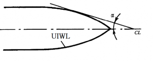
Fig 3.1 Slope of UIWL at the section considerd, (deg)
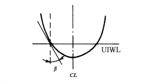
Fig 3.2 Slope of frame on the level of UIWL at the section considerd, (deg
![]()
Fig 3.3 Slope of UIWL at the fore perpendicular, (deg)
![]()
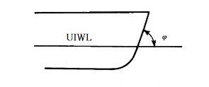
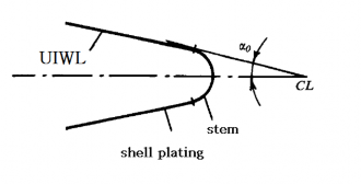
Fig 3.4 Slope of stem on the level of UIWL, (deg)
2. The hull configuration factors of Arc class ships shall be accordance with Table 3.4.
Table 3.4 Hull configuration factor(max. value)
Arc class | Arc5, Arc6 | Arc4, Arc3 | Arc2 | Arc1 |
25° | 30° | 45° | 60° | |
30° | 30° | 40° | 40° | |
within 0,05 from fore perpendicular | 45° | 40° | 25° | 20° |
amidships | 15° | - | - | - |
3. The value of hull configuration factors in Icebreakers shall comply with the following requirements.
(1) At 0 - 0.25L from fore perpendicular at service draughts, straight and convex waterlines shall be used. The entrance angle for above waterlines shall be 22 to 30 .
(2) At service draughts, the angle shall not exceed : 30 for Icebreaker3, Icebreaker4 class ice breakers, 25 for Icebreaker5, Icebreaker6.
(3) The cross section of stem shall be executed in the form of a trapezoid with a bulging forward face.
(4) For Icebreakers with standard bow lines, slop angles of frames shall be adopted from Table 3.5.
(5) In way of construction water line, frames shall have a shape.
straight-lined or moderately convex
Table 3.5 The angle of Icebreaker
Distance from section to fore perpendicular | 0.1 | 0.2 - 0.25 | 0.4 - 0.6 | 0.8 - 1.0 |
(deg) | 40° - 55° | 23° - 32° | 15° - 20° | Approximately coinciding with the angles of within 0 - 0.2 |
![]()
4. The lower ice waterline shall cover the blade tips of side clearance shall not be less than stated in Table 3.6.
propellers(refer to Fig 3.5), the tip
![]()
Fig 3.5 The position of blade tips of side propellers
Table 3.6 The tip clearance
Class of Icebreaker | Icebreaker6 | Icebreaker5 | Icebreaker4 | Icebreaker3 |
Clearance, (mm) | 1500 | 1250 | 750 | 500 |
5. In the afterbody of Icebreakers and Arc class ships, there shall be appendage(ice knife) aft of the rudder to protect the latter on the sternway.
6. For Icebreakers and Arc3 ∼ Arc6 class ships, the transom stern is not permitted. But transom
stern where placed in out of ice strengthening regions is permitted.
7. For Icebreakers and Arc3 ∼ Arc6 class ships, there shall be a ice skeg(refer to Fig 3.6) in the
lower part of the stem. The height of the ice skeg shall be ice skeg to the lower part of the stem shall be smooth.
8. In Arc2 ∼ Arc6 class ships, bulbous bow is not permitted.
is subject to special consideration by the Society.
0.1 at least. The transition from the In Arc1 class ships, this kind of bow
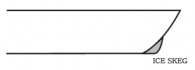
Fig 3.6 Ice skeg
203. Region of ice strengthening
1. There are ice strengthening regions lengthwise as follows. forward region - A
forward intermediate region - B
midship region - C
aft region - D
2. There are ice strengthening regions transversely as follows.
![]()
region from , the upper of UIWL to , the lower of LIWL - 1
region from the lower edge of region 1 to the upper edge of bilge strake - 2 bilge strake - 3
region from the lower edge of bilge strake to the center line - 4
3. The scope of regions of ice strengthening in Arc class ships shall be determined on the basis of
Fig 3.7 and Table 3.7.
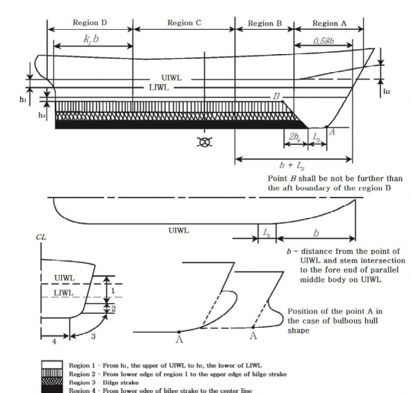
Fig 3.7 Region of ice strengthening of Arc class ships
![]()
Table 3.7 Ice strengthening in Arc class ship
Arc class | Arc4, Arc5, Arc6 | Arc2, Arc3 | Arc1 |
(m) | where ≤ m | 0.75 | 0.60 |
where m | |||
(m) | 1.4 | 0.8 | 0.6 |
(m) | 1.6 | 1.35 | 1.20 |
(m) | 0.15 | 0.1 | 0.05 |
(m) | 0.06 | 0.05 | 0.045 |
0.84 | 0.69 | 0.55 |
4. The scope of regions of ice strengthening
3.8 and Table 3.8.
in Icebreakers shall be determined on the basis of Fig
Table 3.8 Ice strengthening in Icebreaker
Icebreakers | Icebreaker6 | Icebreaker5 | Icebreaker4 | Icebreaker | 3 | ||
, in m | wher ≤ | e m | 1.00 | 0.80 | 0.75 | ||
wher | e m | ||||||
, in m | 2 | 1.7 | 1.4 | 1.1 | |||
, in m | ≥ | ≥ | ≥ | ||||
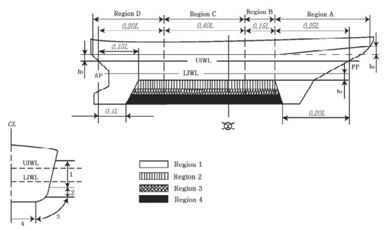
Fig 3.8 Region of ice strengthening of Icebreakers
![]()
5. The requirements of the Chapter apply to the regions of ice strengthening marked with "○" in
Table 3.9. For the purpose of Table 3.9, the absence of this mark means gion of ice strengthening is not covered by the requirements of the section.
that the particular re-
Table 3.9 The requirements of 203. apply to the regions
Ship class | Regions transversely | |||||||||||||||
1 | 2 | 3 | 4 | |||||||||||||
Regions lengthwise | ||||||||||||||||
A | B | C | D | A | B | C | D | A | B | C | D | A | B | C | D | |
Icebreaker4, Icebreaker5, Icebreaker6, Arc5, Arc6 | ○ | ○ | ○ | ○ | ○ | ○ | ○ | ○ | ○ | ○ | ○ | ○ | ○ | ○ | ○ | ○ |
Arc4 | ○ | ○ | ○ | ○ | ○ | ○ | ○ | ○ | ○ | ○ | ○ | ○ | ○ | ○ | ○ | |
Icebreaker3, Arc3 | ○ | ○ | ○ | ○ | ○ | ○ | ○ | ○ | ○ | ○ | ○ | ○ | ○ | ○ | ○ | |
Arc2 | ○ | ○ | ○ | ○ | ○ | ○ | ○ | ○ | ○ | ○ | ○ | ○ | ||||
Arc1 | ○ | ○ | ○ | ○ | ○ | ○ | ○ | ○ | ○ | ○ | ○ | |||||
204. Material and Welding
1. Design temperatures
The design temperatures for steel grades to be used in hull structure members in accordance with
this chapter are to be determined as follows. Where the builder specified the
design temperature
lower than below temperature, the steel grades are to be based on the temperature are specified by the builder.
(1) Arc2 ~ Arc6 and Icebreaker4 ~ Icebreaker6 class ships : -40℃
(2) Arc1 and Icebreaker3 class ships : -30℃
2. Application of steels
(1) Materials for ships applied by the requirements of this chapter in accordance with this chapter
in the various strength members above the LIWL than those corresponding to classes as given in
exposed to air are not to be of lower grades
Table 3.10, For non-exposed structures and
structures below the LIWL, see Pt 3, Ch 1, 405. of the Rules for the Classification of Steel Ships.
(2) The material grade requirements for hull members of each class depending on thickness and de- sign temperature are defined in Table 3.11.
(3) Single strakes required to be of class Ⅲ or of grade E, EH 32/EH 36/EH 40 and FH 32/FH
36/FH 40 are to have breadths not less than the values given by the following formula, max-
imum 1800 mm.
(mm)
(4) Plating materials for stern frames, rudder horns, rudders and shaft brackets are not to be of lower grades than those corresponding to the material classes given in Pt 3, Ch 1, 405. 3 of the Rules for the Classification of Steel Ships.
3. Welding
(1) All welding within ice strengthened regions is to be of the double continuous type.
(2) Continuity of strength is to be ensured at all structural connections.
![]()
![]()
Table 3.11 Application of material classes and grades - Structures exposed at low temperatures
Structural member category | Material class | |||
Within 0.4 | amidships | Outside 0.4 | amidships | |
○ SECONDARY: - Deck plating exposed to weather, in general - Side plating above LIWL - Transverse bulkheads above LIWL | I | I | ||
○ PRIMARY: - Strength deck plating [1] - Continuous longitudinal members above strength deck, excluding longitudinal hatch coamings - Longitudinal bulkhead above LIWL - Top wing tank bulkhead above LIWL | II | I | ||
○ SPECIAL: - Sheer strake at strength deck [2] - Stringer plate in strength deck [2] - Deck strake at longitudinal bulkhead [3] - Continuous longitudinal hatch coamings [4] | III | II | ||
○ Shell plating, frame and welded stem/sten of ice strengthening region 1 for Arc1 class ships | I | I | ||
○ Shell plating, frame and welded stem/sten of ice strengthening region 1 for Arc2 ~ Arc6 class ships and Icebreakers | II | II | ||
Notes : [1] Plating at corners of large hatch openings to be specially considered. Class Ⅲ or grade E , EH 32, EH 36 and EH 40 to be applied in positions where high local stresses may occur. [2] Not to be less than grade E , EH 32, EH 36 and EH 40 within 0.4 amidships in ships with length exceeding 250 m [3] In ships with a breadth exceeding 70 m at least three deck strakes to be class Ⅲ. [4] Not to be less than grade D, DH 32, DH 36 and DH 40. | ||||
![]()
Table 3.12 Material grade requirements for classes I, II and III at low temperatures Class I
Plate thickness in (mm) | -20/-25 °C | -26/-35 °C | -36/-45 °C | -46/-55 °C | ||||
M S | H T | M S | H T | M S | H T | M S | H T | |
≤ | A | A H | B | A H | D | D H | D | D H |
≤ | B | A H | D | D H | D | D H | D | D H |
≤ | B | A H | D | D H | D | D H | E | E H |
≤ | D | D H | D | D H | D | D H | E | E H |
≤ | D | D H | D | D H | E | E H | E | E H |
≤ | D | D H | D | D H | E | E H | E | E H |
≤ | D | D H | E | E H | E | E H | - | F H |
≤ | E | E H | E | E H | - | F H | - | F H |
Class Ⅱ
Plate thickness in (mm) | -20/-25 °C | -26/-35 °C | -36/-45 °C | -46/-55 °C | ||||
M S | H T | M S | H T | M S | H T | M S | H T | |
≤ | B | A H | D | D H | D | D H | E | E H |
≤ | D | D H | D | D H | E | E H | E | E H |
≤ | D | D H | E | E H | E | E H | - | F H |
≤ | E | E H | E | E H | - | F H | - | F H |
≤ | E | E H | - | F H | - | F H | - | - |
≤ | E | E H | - | F H | - | F H | - | - |
Class Ⅲ
Plate thickness in (mm) | -20/-25 °C | -26/-35 °C | -36/-45 °C | -46/-55 °C | ||||
M S | H T | M S | H T | M S | H T | M S | H T | |
≤ | D | D H | D | D H | E | E H | E | E H |
≤ | D | D H | E | E H | E | E H | - | F H |
≤ | E | E H | E | E H | - | F H | - | F H |
≤ | E | E H | E | E H | - | F H | - | F H |
≤ | E | E H | - | F H | - | F H | - | - |
≤ | E | E H | - | F H | - | F H | - | - |
≤ | - | F H | - | F H | - | - | - | - |
Notes : The symbols in the table mean the grades of steel as follows :
AH : AH 32, AH 36 and AH 40, D H : D H 32, D H 36 and D H 40, EH : EH 32, EH 36 and EH 40,
FH : FH 32, FH 36 and FH 40
M S : Mild steels,
H T : High tensile steels
![]()
205. Structure
1. Side grillage structure transversely framed
(1) Side grillage structure transversely framed include conventional frames, deep frames and stringers.
Conventional frame are subdivided into :
- main frames in plane of floors or bilge brackets
- intermediate frame not in plane as floors or bilge brackets. The intermediate frames are not mandatory within a side grillage. Not more than one intermediate frame may be fitted be- tween main frames.
Stringer are subdivided into :
- side stringers by which a transition of forces is ensured from conventional frames which directly take up the ice load to deep frames or to transverse bulkhead
- intercostal stringers by which joint taking-up of local ice loads by the frames is ensured. It is recommended that the stringer shall be inter-costal
(2) Side grillage structures are permitted as follows :
- grillage with transverse main frames which is formed by conventional frames of the same section and by intercostal stringer
- grillage with transverse web frames which is formed by conventional frames, side stringers and deep frames. Intercostal stringers may be fitted together with side stringers
(3)
(4)
(5)
(6)
With a double-bottom structure available, the functions of deep frames are taken over by verti- cal diaphragms, and those of the side stringers, by horizontal diaphragms.
In Icebreakers and Arc2 ~ Arc6 class ships, frames shall be attached to decks and platforms with brackets; if a frame is intercostal in way of deck, platform or side stringer, brackets shall
be fitted on both sides of it.
The end attachments of main frames shall not less than their section modulus. In Icebreakers solid floors shall be fitted on each main frame. In Arc5, Arc6 class ships, solid floors shall be fitted on every other main frame.
In Icebreakers and Arc class ships, the bottom ends of intermediate frames shall be secured at margin plate stiffened with a lightened margin bracket(or a system of stiffeners) reaching up to
longitudinal stiffeners or intercostal members and welded thereto(Fig. 3.9)
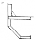
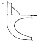
Fig 3.9 - lighted margin bracket, - system of
(7) Where there is no double bottom, the intermediate frames shall extend as far as longitudinal stiffeners or intercostal structure and welded thereto. The particular longitudinal stiffener or inter- costal structure shall be fitted not higher than the floor face-plate level.
(8) In Icebreakers and Arc class ships, the upper ends of intermediate frames shall be secured on a deck or platform lying above the upper boundary of region I.
(9)
In region I and II of Icebreakers and Arc class ships, intercostal and/or side stringers shall be
fitted the distance between which or the stringer-to-deck or platform distance shall not exceed 2m, as measured on a chord at side.
Side stringers shall be fitted in the UIWL and LIWL regions. If there is a deck or platform ly- ing on the same level, the side stringer may be omitted. Stringers shall be attached to bulkhead
by means of brackets.
2. Supporting sections of frames in grillage with transverse framing
![]()
(1) For frames, horizontal grillages(decks, platforms, bottom) are considered to be supporting structures. A supporting structure consists of plating(decks, platforms, double bottom) and fram- ing connected thereto(beams, half-beams, floors, tank-side brackets). Where there is no double
![]()
(2)
bottom, the formulate to be found below shall be used on the assumption that the plating lies level with floor face plates.
The supporting section of a conventional frame is considered to be fixed, if one of the follow- ing conditions is met at least.(refer to Table 3.12)
1) the frame is connected to the framing of a supporting structure
2) the frame crossed the plating of a supporting structure
(3) A supporting section is considered to be simply supported, if one of the following conditions is
met at least.(refer to Table 3.12)
1) a conventional frame is not connected to supporting structure framing
2) a conventional frame is terminated on the structure plating
(4)
(5)
Where a conventional frame terminates on an intercostal longitudinal(intercostal stringer), its end is considered to be free, i.e. with no supporting section.
The position of a supporting section of a frame(conventional or deep frame) is determined in
the following way.(refer to Table 3.12)
1) Where the frame is connected to the supporting structure plating only, the supporting section coincides with the plating surface.
2) Where the frame is connected to the supporting structure framing, the supporting section
coincides with the face plate surface of the supporting structure frame in case of bracketless joint.
3) Where the frame is connected to the supporting structure framing, the supporting section lies
at bracket end where brackets nected.
4) Where the frame is connected to
with a straight or rounded and stiffened edge are con
the supporting structure framing, the supporting section lies
in the middle of the bracket side where brackets with a rounded free edge connected.
are
![]()
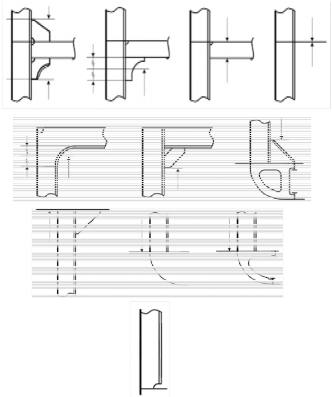
Table 3.12 Structure and the position of supporting section of transverse framing
frames in grillage with
Type of joint in way supporting section of the frame | Type of supporting section | Sketch showing structure and the position of supporting section therein |
Intersection of supporting structure | Fixed | |
Securing on supporting structure with connection to its framing | Fixed | |
Securing on supporting structure without connection to its framing | Simply supported | |
Securing on intercostal longitudinal | Free end | No supporting section |
![]()
4. Plate structures
(1) By plate structures, the sections of deck, platform and double bottom plating, of transverse bulkhead plating, deep frame plates and bilge brackets which adjoin the shell plating are meant.
(2) For hull members mentioned under (1), the areas to be covered by the requirements for plate
structure shall be established as Table 3.13.
Table 3.13 Application area of the requirements for plate structure
Area | Ship class | Distance from the shell plating |
fore peak and after peak bulkheads | Icebreakers and Arc2 ~ Arc6 | throughout their breadth |
other bulkheads in region 1 and 2 | Icebreakers and Arc1 ~ Arc6 | on a breadth of 1.2m |
decks and platforms | ||
other hull members | on a breadth of 0.6m |
(3) In the areas of plate structures mentioned under (2), corrugated structures with corrugations ar- ranged along the shell plating(i.e. vertical corrugations on transverse bulkheads and longitudinal corrugations on decks or platforms) are not permitted.
(4) The plate structures of Icebreakers, Arc2 ~ Arc6 class ships and region 1 of Arc1 class ships shall be provided with stiffeners fitted at right angles approximately to the shell plating. The stiffeners shall be spaced not farther apart than stipulated in Table 3.14.
Table 3.14 Maximum spacing of stiffeners
Orientation of main framing fitted at shell plating | Maximum spacing of stiffeners | |
Icebreaker(region 1) Arc3 ~ Arc6 | Arc2(except region 1), Arc1(region 1) | |
Main framing lies across a plate structure | , but not greater than 0.5 m | , but not greater than 1.0 m |
Main framing lies parallel to plate structure | 0.6 m | 0.8 m |
Note : is the spacing of main framing girder, as measured on the shell plating. | ||
(5)The intersections of plate structures with
Table 3.14.
main framing shall be executed in accordance with
![]()
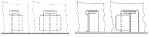
Table 3.14 The intersections of plate structures with main framing
Ship class | Sketch of structure | ||
| |||
Icebreaker5, Icebreaker6 | Fore peak, after peak, region 1, 2 with longitudinal framing | Regions 2, A3, B3, D3, A4, B4 | Other regions as per Table 3.9 |
Icebreaker3, Icebreaker4 | Fore peak, after peak, region 1, 2 with longitudinal framing | Regions 1 and 2 (except fore peak and after peak) A3, B3, D3 | |
Arc4 ~ Arc6 | Fore peak, region 1 with longitudinal framing | Regions 1 and 2 (except fore peak), A3, A4, B3, B4 | |
Arc2, Arc3 | Fore peak, region A1, B1, C1 with longitudinal framing | Regions 1 (except fore peak), 2 , A3, B3 | |
Arc1 | ㅡ | Regions 1, A2, B2, A3, B3 | |
(6) Where main framing girders are intercostal in way of the plate structure, brackets shall be fitted on both side of the structure on the same plane as each of the girders, and the girder webs shall be welded to the plate structure.
(7) The following requirements are put forward additionally for the intersections of the plate struc- tures of decks and platforms with main framing.
1) Where transverse framing is used for sides, the frames shall be attached to the beams with brackets, In Arc2(region 1 only), Arc3 ~ Arc6 class ships, the girders shall be fitted on the
same plane as each of the frames.
2) In Arc2(except region 1) and Arc1(region 1) class ships, the frame on whose plane no beam is fitted shall be secured to the plate structure with brackets which shall terminate on the intercostal stiffener.
3) Where longitudinal framing is used for sides, the beams shall be attached to the shell plating with brackets reaching as far as the nearest side longitudinal.
(8) The distance from the edge of opening or manhole to the shell plating shall not be less than
0.5m in a plate structure. The distance from the edge of opening or manhole in a plate struc- ture to the edge of opening for the passage of a girder through the plate structure shall not be less than the height of that girder.
5. Fore peak and after peak structure
(1) A longitudinal bulkhead welded to the stem or sternframe shall be fitted on the centerline of the ship in the fore peak and after peak of Icebreakers and Arc5, Arc6 class ships, and the lower ends of all frames shall be connected to floors or brackets.
(2) In the fore peak of Icebreakers and Arc2 ~ Arc6 class ships, platforms with lightening holes shall be fitted instead of stringers and panting beams, the distance between platforms measured along a chord at side, shall not exceed 2.0m. This structure is recommended for Arc1 class ships as well.
(3) In the after peak of Icebreakers and Arc2 ~ Arc6 class ships, side stringers and panting beams shall be fitted so that the distance between the stringers as measured along a chord at side, would not be greater than 2.0m. The dimensions of stringer webs shall not be less than de- termined by the formulae.
![]()
depth d = 5L + 400 (mm) thickness t = 0.05L + 7 (mm) where, L : length of ship (m)
![]()
Platform with lightening holes are recommended instead of panting beams and stringers.
(4) In Icebreakers and Arc3 ~ Arc6 class ships, the side stringers in the fore peak and after peak shall generally be a continuation of those fitted in the region A and D(refer to 203. 1)
(5) In the case of Arc1 class ships, the area and inertia moment of panting beams shall be in-
creased by 25 per cent as compared to those required for non-Arc class ships. The dimension of stringer webs shall not be less than given by the formula.
depth d = 3L + 400 (mm) thickness t = 0.04L + 6.5 (mm) where, L : length of ship (m)
(6) In the fore peak and after peak, the free edge of side stringers shall be stiffened with face plates having a thickness not less than the web thickness and a width not less than ten thickness. The interconnections of frames with side stringers shall be in accordance with Table 3.14, and brackets shall be carried to the face plates of the stringers.
6. Stem and sternframe construction
(1) Arc3 ~ Arc6 class ships shall have a solid section stem made of steel(cast steel is recom- mended). The stems and sternframes of Icebreakers, as well as the sternframes of Arc2 ~ Arc6 class ships, shall be made of forged or cast steel. Stems and sternframes welded of cast or forged parts are admissible.
(2) In Arc1, Arc2 class ships, a stern of combined structure(a bar with thickened plates welded thereto) or plate structure may be used, and where the ship length is under 150m with a sharp- lined bow, the stem design shown in Fig 3.10 may be used.
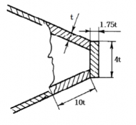
Fig 3.10 Stem for ship length is under 150m
(3) In Arc1 ~ Arc4 class ships, the stem shall, where practicable, be strengthened by a center line web having its section depth equal to at least(refer to Table 3.35) with a face plate along its free edge or a longitudinal bulkhead fitted on the ship centerline, on the entire stem length from the keel plate to the nearest deck or platform situated above the level referred to in
216. and in Table 3.35. The thickness of this plate shall not be less than that of the brackets.
In Icebreakers and Arc5, Arc6 class ships, a longitudinal bulkhead may be substituted for the
(4) center line web.
Within the vertical extent defined in (3), the stem shall be strengthened by horizontal webs at
least 0.6m in depth and spaced not more than 0.6m apart. The webs shall be carried to the nearest frames and connected thereto. Where in line with side stringers, the webs shall be at- tached to them. In stems of combined or plate type, the webs shall be extended beyond the
(5) Above the deck or platform located, by the value of
at least, higher than the upper
dary of region 1, the spacing of horizontal webs may boun- gradually increase to 1.2m in
and Arc4 ~ Arc6 class ships, and to 1.5m in ships of
Icebreakers other classes. The web
(6)
adopted not less than half the stem plate thickness. In Icebreakers and Arc class ships, the free edges of webs shall be strengthened with face plates welded to the frames at their ends. The side stringers of the fore peak shall be connected to the webs fitted in line with them.
Where the stern frame has an appendage(ice knife), the clearance between the latter and the
rudder plate shall not exceed 100mm. The appendage shall be reliably connected to the stern
![]()
frame. Securing the appendage to plate structure is not permitted.
(7) In Icebreakers, the lower edge of sole-piece shall be constructed with a slope of 1:8 beginning from the propeller post.
7. Bottom structure
(1) In Icebreakers and Arc2 ~ Arc6 class ships, double bottom shall be provided between the fore peak bulkhead and the after peak bulkhead.
(2) In Icebreakers, provision shall be made for solid floors at each main frame, and in Arc5, Arc6 class ships, at every other main frame.
(3) In regions of ice strengthening in way of bottom, as established in accordance with Table 3.9, bracket floors are not permitted.
(4) In Icebreaker and Arc5, Arc6 class ships the center-line girder height shall not be less than de- termined by the formula.
where,
= 0.8 for Arc5 class ships
0.9 for Arc6 class ships
1.0 for Icebreakers
(5) In Icebreakers and Arc5, Arc6 class ships, the spacing of bottom stringers shall not exceed 3.0m.
8. Special requirements
(1) In Icebreakers, double side structure shall generally be provided between the fore peak bulkhead and the after peak bulkhead.
(2) In Arc4 ~ Arc6 class ships double side structure is necessary for engine room, and for the re- gion mentioned in (1) it is recommended.
(3) Where the web plate of a girder of a plate structure is considerably inclined to the shell plat-
ing, the framing normal to the shell plating or an inclined plate structure is recommended.
206.
1.
Ice load
Where using the ice load parameters for strength estimation on the basis of other procedures programs are to be specially approved by the Society.
and
2. The ice-load parameters to be determined according to Par 3 to 8 apply to Arc class ships and Icebreakers with hull shape complying with the requirements of 202. 2. and 202.3 .
3. Ice load for Arc class ships
![]()
For Arc class ships, the ice load(kPa), shall be determined by Table 3.16.
![]()
Table 3.16 Ice load for Arc class ships
Ice strengthening region and Arc class | Ice load (kPa) | |
A1 | All class | |
B1 | ||
C1 | ||
D1 | Arc1, Arc2, Arc3 | |
Arc4, Arc5, Arc6 | ||
2, 3, 4 | All class | the ice load is determined as follow formula a part of the ice load in region 1 at considered section · |
Where , , , = factor as specified in Table 3.17 proceeding from the Arc class = displacement(t) correspond to UIWL = value of the shape factor which is the maximum one for the region, as at considered sections on the ice loadline level. The value shall be determined by the formula. where ≤ where = the distance between the considered section and the forward perpendicular(m) = angles(deg) of summer load waterline inclination which shall be measured in accordance with Fig 3.1 and 3.3 (where ) = angles(deg) of frame inclination on UIWL level which shall be measured in accordance with Fig 3.2. Where the frame is concave in a section, a minimal angle shall be chosen for in the case of Arc1 ~ Arc6 class ships which is measured on all waterlines of ice navigation = as specified in Table 3.18. is A, B, C, D for region lengthwise of ice strengthening, is 2, 3, 4 for region transversly of ice strengthening. | ||
![]()
Table 3.17 The value of , , ,
Arc class | Arc1 | Arc2 | Arc3 | Arc4 | Arc5 | Arc6 |
0.79 | 1.15 | 1.89 | 2.95 | 5.3 | 7.9 | |
0.80 | 1.17 | 1.92 | 3.06 | 5.75 | 8.95 | |
0.50 | 0.78 | 1.2 | 1.2 | 3.7 | 5.6 | |
0.75 | 0.87 | 1.0 | - | - | - |
![]()
Table 3.18 The value of
Arc class | Region lengthwise | ||||||||
forward and intermediate regions (A and B) | midship region (C) | aft region(D) | |||||||
Region vertically | |||||||||
2 | 3 | 4 | 2 | 3 | 4 | 2 | 3 | 4 | |
Arc1 | 0.5 | 0.4 | 0.35 | 0.4 | - | - | - | - | - |
Arc2 | 0.65 | 0.65 | 0.45 | 0.5 | 0.4 | - | 0.5 | - | - |
Arc3 | 0.65 | 0.65 | 0.5 | 0.5 | 0.45 | - | 0.5 | 0.35 | 0.15 |
Arc4 | 0.65 | 0.65 | 0.5 | 0.5 | 0.45 | - | 0.5 | 0.4 | 0.2 |
Arc5 | 0.7 | 0.65 | 0.5 | 0.55 | 0.45 | 0.25 | 0.55 | 0.4 | 0.3 |
Arc6 | 0.7 | 0.65 | 0.5 | 0.55 | 0.45 | 0.3 | 0.55 | 0.4 | 0.35 |
4. The vertical distribution height of ice load for Arc class ships
![]()
Ice strengthening region and Arc class | Vertical distribution height | |
A | All class | |
B | Max. : Min. : | |
C | ||
D | Arc1, Arc2, Arc3 | |
Arc4, Arc5, Arc6 | ||
Where , , = factor as specified in Table 3.20 proceeding from the Arc class = factor as specified in Table 3.21 proceeding from the minimal side inclination angle in the midship region of ice strengthening on UWIL ∆ , but not greater than 3.5 = refer to Par 3 = value of the shape factor which is the maximum one for the region, as at considered sections on the ice loadline level. The value shall be determined by the formula. , where ≤ , where , where ≥ , where = refer to Par 3 , , = refer to Par 3 | ||
The vertical distribution height(m) of ice load shall be determined by the following Table 3.19. Table 3.19 The vertical distribution height of ice load for Arc class ships
![]()
Table 3.20 The value of , ,
Arc class | Arc1 | Arc2 | Arc3 | Arc4, Arc5, Arc6 |
C1 | 0.49 | 0.6 | 0.62 | 0.64 |
C2 | 0.55 | 0.7 | 0.73 | 0.75 |
C3 | 0.34 | 0.40 | 0.47 | 0.50 |
Table 3.21 The value of
Angle of side slope amidships(deg) | ≤6 | 8 | 10 | 12 | 14 | 16 | 18 |
1.00 | 0.81 | 0.68 | 0.54 | 0.52 | 0.47 | 0.44 |
5. The horizontal distribution length of ice load for Arc class ships
Horizontal distribution length(m) of ice load, shall be determined by the following Table 3.22.
Table 3.22 The horizontal distribution length of ice load for Arc class ships
Ice strengthening region | Horizontal distribution length |
A | sin , but not less than |
B | , but not less than |
C | but not less than |
D | but not less than |
Where , , , , ∆ = refer to Par 4 = angle in the design section of region A for which the value of the parameter is maximum = angle in the design section of region B for which the value of the parameter is maximum = refer to Par 4 | |
6. Ice load for Icebreakers
For Icebreakers, the ice load shall be determined by the following Table 3.23.
![]()
Table 3.23 The ice load for Icebreakers
Region | Ice load |
A1 | |
B1, C1, D1 | |
2, 3, 4 | |
Where = ice load in region A1, to be determined in accordance with Par 3 as in the case of a ship whose ice class number coincides with the class of the Icebreaker = 1, where ∑ ≤ ∑ , where = propeller shaft output(MW) (MW) = as specified in Table 3.24 = factor as specified in Table 3.25 proceeding from the region of the ship length and class of Icebreaker = ice load in region 1 proceeding from the region lengthwise, , , , = parameter as specified in Table 3.26, is A, B, C, D for region lengthwise of ice strengthening is 2,3,4 for region transversly of ice strengthening. | |
Table 3.24 The value of
Icebreakers | |
Icebreaker3 | 10 |
Icebreaker4 | 20 |
Icebreaker5 | 40 |
Icebreaker6 | 60 |
Table 3.25 The value of
Region | Icebreakers | |||
Icebreaker3 | Icebreaker4 | Icebreaker5 | Icebreaker6 | |
B1 | 0.65 | 0.75 | 0.85 | 0.85 |
C1 | 0.6 | 0.65 | 0.7 | 0.75 |
D1 | 0.75 | 0.75 | 0.75 | 0.75 |
Table 3.26 The value of
Region vertically and region lengthwise | A2 | A3 | A4 | B2 | B3 | B4 | C2 | C3 | C4 | D2 | D3 | D4 |
0.7 | 0.65 | 0.5 | 0.6 | 0.55 | 0.45 | 0.55 | 0.45 | 0.35 | 0.55 | 0.40 | 0.30 |
7. As far as Icebreakers are concerned, the vertical equal for all regions and shall be determined in
distribution height of ice pressure shall be adopted accordance with Par 4, i.e. when determining ,
the values of shall be calculated for those sections only which are included in the forward
re- gion A of ice strengthening of the Icebreaker.
8. As far as Icebreakers are concerned, the horizontal distribution length of ice pressure shall be adopted equal for all regions are shall be determined in accordance with Par 5, i.e. when determin-
ing
, the values of shall be calculated for those sections only which are included in
![]()
forward region A of ice strengthening of the Icebreaker.
![]()
207. Shell plating
In regions of ice strengthening, the shell plating thickness (mm), by the formula. In addition, (mm) shall not be less
than the Rules for the Classificaion of Steel Ships.
shall not be less than determined requirements of Pt 4, Ch 4 of
(mm)
where
= ice load(kPa) in the region under consideration according
to 206. 3. or 206. 6.
= where the grillage is transversely framed in the region under consideration. In this case, shall not be greater than the spacing of intercostal stringers or
the
= distance between plate structures
= where the grillage is longitudinally framed in the region under consideration
vertical distribution(m) of ice pressure in the region under consideration according
= distance between supporting section of longitudinal frame(m)
= spacing of longitudinal frame for the grillage is longitudinally framed or of transverse frame for the grillage is transversely framed(m)
∆ = additional thickness(mm) for corrosion wear and abrasion, as specified in Table 3.27.
Table 3.27 Additional thickness, ∆ for corrosion wear and
Ship class | Region of ice strengthening | |
forward and intermediate (A and B) | midship and after(C and D) | |
Arc1 | 7.0 | 5.0 |
Arc2 | 7.0 | 5.5 |
Arc3 ~ Arc6 | 7.5 | 5.5 |
Icebreaker3 | 7.5 | 5.5 |
Icebreaker4 | 9.5 | 6.5 |
Icebreaker5 | 11.5 | 7.5 |
Icebreaker6 | 13.0 | 7.5 |
208. Procedure for determining the actual section area and ultimate section modulus of stiffeners
The procedure for determining the actual section area and ultimate specified in Ch 2, 205.
section modulus of stiffeners are
209. Conventional frames where transverse framing is used
The requirements of this paragraph apply to conventional frames, main frame and deep frame in
![]()
grillages where transverse framing is used. In the case of main framing, the requirements shall be applied to a single span of a conventional frame which lies between the supporting sections of the frame on the upper and lower supporting structures. In the case of web frames, the requirements shall be applied to all the spans of a conventional frame.
1. The ultimate section modulus the formula.
(cm3), of a conventional frame shall not be less than determined by
3
(cm )
where
= 1 with
= 0.5 with < 4
= refer to Table 3.28 for grillage with main framing
= 4 for grill ages with web framing
= factor equal to : the number of fixed supporting sections of two adjacent frames ≤
as far as grillage with main framing are concerned, in the case of grillage with web framing, refer to Table 3.28
= ice load(kPa) in the region under consideration in accordance with 206. 3. or 206. 6. where the lower boundary of region 1 is included in the grillage and this requirements cover region of ice strengthening 1 and 2, the following values of shall be adopted
, if the distance from the plating of the upper supporting structure of the grillage the lower boundary of region 1 is greater than 1.2b, other wise =
, = ice load in regions 1 and 2(refer to 206. 3.)
= vertical distribution(m) of ice load in the region under consideration in accordance with
206. 3. or 206. 6. if b > l, b = 1 shall be adopted for the purpose of determining and
= conventional frame spacing(m) as measured at side
= considered frame span(m) to be determined in accordance with Table 3.28 in the case of main framing and with Table 3.29 in the case of web framing
= factor equal to 0.9 for conventional frames joined with knees to bearing stringers in a side grillage with deep frames, and equal to 1.0 in other cases
E = factor equal to :
with
with ≥
![]()
where = section of the span length (m) overlapped by the region of ice
![]()
Table 3.28 The parameter and
Parameter | Type of intermediate frame end fixation | ||
both ends supported | one end supported, the other free (attached to an intercostal member) | both ends free (attached to an inter costal member) | |
4 | 3 | 2 | |
Half the sum of distances between the supporting sections of two adjacent frames | Distance between the supporting sections of main frame | ||
Table 3.29 The parameter and
Position of conventional frame zone under consideration | ||
Between side stringers | Distance between side stringers | 4 |
Between upper (lower) supporting structure and the nearest side stringer | Half the sum of distances between supporting sections on supporting structure and the nearest side stringer for two adjacent frames | where ≤ is the number of fixed supporting sections on the supporting structure for two adjacent frames |
2. The web area (cm2) of a conventional frame shall not be less than determined by the formula.
(cm2)
where
or whichever is
distance
= refer to Par 1, the values of and adopted shall not exceed he
between bracket ends
= 1 - where no side stringer is provided
0.9 - where there is a side stringer in the span
= frame web height(cm), for symmetric bulb and for asymmetric bulb
3. The actual web area
![]()
(cm2), shall be determined in accordance with Ch 2, 205.
![]()
4. The web thickness (mm), of a conventional frame shall be adopted not less than the greater of the following values.
(mm) or
(mm)
Where
= , but not less than =
3
= actual ultimate section modulus(cm ), of a conventional frame, to be determined in
accordance with 208.
, = refer to Par 1
, ∆ = refer to Par 2
5. The face plate breadth (mm), of a conventional frame shall not be less than the greater one of the following values.
(mm) or
(mm) or
(mm)
where
, = refer to Par 1
= refer to Par 4
= actual web thickness of a conventional frame(mm)
= face plate breadth(mm) of a conventional frame(for beams made of bulbs, shall be adopted)
= refer to Par 2
but not less than =
= the greatest spacing(m), of adjacent stringers crossing the frame span or the greatest
, but not less than = 1
= actual shell plating thickness(mm)
6. Where the face plate breadth is not in accordance with shall not be less than determined by the formula. A
Par 5, the height of a conventional frame distance between side stringers or a side
stringer and a supporting structure for conventional frames shall not exceed 1.3 m.
(cm)
where = refer to Par
![]()
∆ = refer to Par
210. Side and intercostal stringers as part of transverse framing with deep frames
1. The ultimate section modulus (cm3) of a bearing side stringer by the formula.
shall not be less than determined
(cm3)
where
(cm3)
side
= refer to 209.
= deep frame spacing(m) as measured along the
≥ with ≥
≥ with
= refer to 206. 5.
with with ≥
2. The web area (cm2), of a side stringer shall not be less than determined by the formula.
2
(cm )
where
= refer to 209. 1.
= number of frames fitted between considered side stringers
, = refer to Par 1
= web height of a side stringer(cm)
= refer to 209. 2.
3. The actual web area (cm2), of a side stringer shall be determined in accordance with Ch 2, 205.
4. The web thickness (mm), of a side stringer shall not be less than determined by the formula
(mm)
where
![]()
the shorter and longer side, in m, of the divided by its stiffeners for an unstiffened web,
panels into which the stringer web is
![]()
= refer to 209. 2.
= refer to Par 1
, = Par 2, 3
= refer to 209. 2.
5. The web height (cm), of a side stringer shall not be less than determined by the formula
(cm) where
= refer to 209. 2.
6. The face plate thickness of a side stringer shall not be less than its actual web thickness. The side stringer without face plate is not permitted.
7. The face plate breadth (mm), of a side stringer shall not be less than the greater of the follow- ing values
(mm) or
where
= refer to Par 1
3
= actual ultimate section modulus (cm ), of aside stringer, to be determined in accordance
with Ch 2, 205.
= face plate thickness (mm), of a
= actual web thickness of a stringer
= refer to Par 2
8. The web height (cm), of an intercostal stringer in way of a conventional frame shall not be less than determined by the formula
(cm) where
= refer to 209. 2.
9. The web thickness of an intercostal stringer shall not be less than that of a conventional frame, as required in accordance with 209. 4.
211. Deep frames as part of transverse framing
1. The ultimate section modulus (cm3) of a deep frame shall not be less than determined by the formula.
(cm3)
![]()
where
= refer to Table 3.31
= number of frames fitted between considered deep frames with
with
, = factors to be determined from Table 3.32
= refer to 210. 1.
= factor to be adopted equal to the lesser of the following or
= refer to 209. 1.
= refer to 209. 4.
≥
= refer to 206. 5.
= refer to 210. 1.
≥ with
= refer to 209.
= span(mm) between supporting section of a deep frames
Table 3.31 The value of
1 | 2 | 3 | 4 | 5 | 6 | |
1.0 | 1.33 | 2.0 | 2.4 | 3.0 | 3.43 |
Table 3.32 The value of ,
3 | 4 | 5 | 6 | |
0.5 | 0.417 | 0.333 | 0.292 | |
0.25 | 0.167 | 0.111 | 0.083 |
2. The web area (cm2) of a deep frame shall not be less than determined by the formula.
(cm2)
where
209. 1.
= refer to
, = refer to Par
![]()
= deep frame web depth (cm)
∆ = refer to 209. 2.
3. The actual web area (cm2) of a deep frame shall be determined in accordance with Ch 2, 205.
4. The web thickness (mm) shall be adopted not less than the greater of the following
(mm) or
(mm)
where
, but not less than
3
= actual ultimate section modulus (cm ) of a deep frame to be determined in accordance with Ch 2, 205.
= refer to 206. 3. (1)
= refer to Par 1
= refer to Par 2
= refer to Par 3
= the shorter and the longer side(m) of panels into which the web of a deep frame is divided by its stiffeners
= refer to 209. 2.
5. The face plate thickness of a deep frame shall not be less than the actual thickness of its web.
Deep frame without face plate is not permitted.
6. The face plate breadth values.
(mm) of a deep frame shall not be less than the greater of the following
(mm) or
(mm)
where
= refer to Par 1
refer to Par 4
= face plate thickness(mm) of a deep frame
= web thickness(mm) of a deep frame
= refer to Par 2
, , = refer to Table 3.33
![]()
Table 3.33 The value of , ,
if the web plating | is | provided | with | stiffeners | fitted | normal | to | the | shell | 0.0039 | 1.4 | 5 |
if the web plating | is | provided | with | stiffeners | fitted | parallel | to | the | shell | 0.0182 | 2.6 | 10 |
if it is unstiffened | ||||||||||||
212. Side and bottom longitudinals as part of longitudinal framing
1. The ultimate section modulus (cm3) of a longitudinal formula.
shall not be less than determined by the
(cm3)
where
(cm3)
= refer to 209. 1.
= spacing(m) of deep frames or floors
with
with ≥
= spacing(m) of longitudinals
= 1, for bottom longitudinals and for side are fitted
longitudinals where no panting frames
, for side longitudinals where panting frames are fitted
2. The web area (cm2) of a longitudinal shall not be less than determined by the formula.
2
where
= refer to 209. 1.
= refer to Par 1
= factor to be adopted as the greater of the
![]()
, or
= web height (cm) of a longitudinal
∆ = refer to 209. 2.
3. The actual web area (cm2) of a longitudinal shall be determined in accordance with Ch 2, 205.
4. The web area (mm) of a longitudinal shall be adopted not less than the greater one of the follow- ing values.
(mm) or
(mm)
where
, but not less than
3
= actual ultimate section modulus (cm ) of a longitudinal, to be determined in accordance with Ch 2, 205.
= refer to 209. 1.
= refer to Par 1
= refer to Par 2
∆ = refer to 209. 2.
5. The face plate breadth (mm) of a longitudinal shall not be less than the greater of the following values.
(mm) or
(mm)
where
= refer to Par 1
= refer to Par
= actual web thickness(mm) of a longitudinal
face plate thickness(mm) of a longitudinal(for longitudinals of bulb, shall be
adopted)
but not less than
, but not less than
= actual shell plating thickness(mm)
= refer to Par 1
= span(m) of a
![]()
6. Where the face plate breadth is not in accordance with Par 5, the height of a longitudinal shall not be less than the value determined by 209. 6.(where shall be assumed equal to ). A tance between deep frames or a deep frame and a supporting structure for longitudinals without
face plates shall not exceed 1.3 m.
213. Deep frames as part of longitudinal framing
1. The ultimate section modulus formula.
(cm3) of a deep frame shall
not be less than determined by the
(cm3)
where
, = refer to 209.
1.
= refer to 211. 1.
= refer to
= refer to 212. 1.
= factor to be adopted as the lesser of the
or
= number of longitudinals in considered transverse span
2. The web area (cm2) of a deep frame shall not be less than determined by the formula.
(cm2)
where
, = refer to 209. 1.
= refer to 212. 1.
= transverse web height(cm)
∆ = refer to 209. 2.
3. The actual web area (cm2) of a deep frame shall be determined in accordance with Ch 2, 205.
4. The web thickness of a deep frame shall not be less than the greater of the values determined by
211. 4, while is required ultimate section modulus(cm3) of a transverse shall be in accordance with Par 1 and is spacing(m) of longitudinals. The requirements of this paragraph apply to the
vertical diaphragms of the double side.
5. The web height of a deep frame shall not be less than determined by the formula. (cm)
![]()
where
= web height (cm) of a longitudinal
6. The face plate thickness of a transverse shall not be less than its actual web thickness.
7. The face plate breadth of a transverse shall be determined in accordance with 211. 6. while shall be in accordance with Par 1. The transverse without face plate (flat bar) is not permitted.
214. Additional frames and horizontal diaphragms as part of longitudinal framing
1. The web height of an additional frame (cm) in way of a longitudinal shall not be less than de- termined by the formula.
where
= web height(cm) of a longitudinal
2. The web thickness of an additional frame in accordance with 212. 4.
3. Where the outboard side is longitudinally everse in accordance with 213. 2.
shall not be less than that of a longitudinal, as required framed shall not be less than the web area of a trans-
215. Plate structures
1. The thickness of plate structures forming part of web framing of side grillages(deep frames, side stringers) shall be determined in accordance with 210. 4, 211. 4, 213. 4.
2. The plate structure thickness of decks, platforms, double bottom and bottom girder shall not be less than (mm) to be determined by the formula.
(mm) where
, if the plate structure is shell plating
if the plate structure is unstiffened or parallel to the shell plating
= refer to Table 3.34
1.0
5.
, but not less than
= shall be in accordance with 206.
(1) as far as Icebreakers are concerned
= spacing(m) of stiffeners in a plate structure
= refer to
![]()
∆ = refer to 209.
Table 3.34 The value of
Ship class | |
Arc1, Arc2 | 1.3 |
Arc3, Icebreaker3 | 1.2 |
Arc4, Icebreaker4 | 1.1 |
Arc5, Arc6, Icebreaker5, Icebreaker6 | 1.0 |
3. In addition to the requirements where the side is transversely formula.
of Par 2, the thickness of plate structures in decks and platforms, framed, shall not be less than (mm) to be determined by
(mm)
where
= refer to Par 2
= refer to 209. 1.
= length(m) of unstiffened section of opening in plate structure for the passage of a conventional frame, as measured on the shell plating
= distance(m) from the plate structure under consideration to the nearest plate structures (decks, platforms, side stringers, inner bottom plating) on both sides
= spacing(m) of plate structure stiffeners fitted approximately normal to shell plating
= cross-sectional area of stiffener(cm 2) without effective flange where stiffeners are fitted parallel to the shell plating or snipped, shall be adopted
= refer to 209. 4.
= refer to 209. 2.
∆ = refer to 209. 2.
4. Transverse bulkhead plating thickness where the side is longitudinally framed and the floor and
bilge bracket thickness where the bottom is longitudinally framed shall not be less than be determined by the formula.
(mm)
(mm)
where
![]()
, = refer to Par 2
but not greater than
= spacing(m) of side (bottom) longitudinals
= refer to 209. 1.
= refer to 207.
∆ = refer to 209. 2.
5. The plate structure thickness of transverse bulkheads in a transversely framed side, and of floors in a transversely framed bottom shall not be less than (mm) to be determined by the formula.
(mm) where
than
but not greater
, = refer to Par 2
= refer to Par 4
= spacing(m) of conventional frames (for p1ate structures of bulkheads) or floors (for p1ate structures of floors)
= refer to 207.
∆ = refer to 209. 2.
6. In any case, the plate thickness of decks and platforms, transverse bulkheads, inner bottom, floors and bilge brackets, bottom stringers and centre girder shall not be less than (mm) to be de- termined by the formula.
(mm) where
with ≤ ,
with
with ≥
, for plate structures of, decks and platforms, inner bottom, bottom stringers and centre girder in a longitudinally framed side or bottom
, for the rest of plate structures where the bottom is transversely framed and for all plate structures where the bottom and side are framed transversely
= refer to Par 2
= refer to Par 4
= refer to 209. 1.
= spacing(m) of main framing girders of shell plating
![]()
where the longer side of plate structure panel adjoins the shell plating
4 where the shorter side of plate structure panel adjoins the shell plating
the shorter and longer sides(m) of pane1s into which a p1ate structure is divided by its stiffeners
∆ = refer to 209. 2.
7. The inertia moment (cm4) of stiffeners by which the plate structures are structures and which are fitted normal to the shell plating shell not be less than determined by the formula.
(cm4)
where
span length(m) of stiffener, not greater than
= thickness(mm) of p1ate structure being strengthened spacing(m) of stiffeners
2
sectional area of stiffener(cm ) without effective flange
8. A horizontal grillage adjoining the shell plating in an region of ice strengthening, but not reaching from side to side (deck or platform in way of large openings, horizontal diaphragm of double side, etc.) may be considered a platform if the sectional area of its plating (on one side) is not less than (cm2) to be determined by the formula.
2
(cm )
where
, = refer to 209. 1.
= design distribution length(m) for the load taken up by the transverse main framing of
to be adopted equal to , or to or whichever is less, in the case of framing (transverse or longitudinal) including deep frames
= refer to 206. 5.
= refer to 210. 1.
= refer to Par 3
Otherwise, such a structure shall be considered a bearing side stringer. Structure considered to be a platform shall comply with the requirements of 215. for the plate structures of platforms, and one considered to be a stringer, with the requirements of 210.
216. Stems and sternframes
1. Stems
(1)
The requirements of this paragraph for the section modulus and plate thickness of stem shall be complied on the stem span from the keel to a level extending above the upper boundary of the ice strake by a value of (refer to Table 3.35). In the case of Icebreaker, this stem shall extend up to the nearest deck or platform lying higher than this level.
(2) The cross sectional area (cm2) of stem shall not be less than determined by the formula.
![]()
2
(cm )
where
refer to Table 3.35
(2cm ) with (cm2) with ≥
(3) The stem above the borders of the area considered shall not be less than determined by the formula.
(1), the scantlings may gradually reduce and
The cross sectional area : (cm2) The thickness : · (mm)
where
= The shell plating thickness of region
A1
Table 3.35
Ship Class | Arc1 | Arc2 | Arc3 | Arc4 | Arc5 | Arc6 | Ice breaker3 | Ice breaker4 | Ice breaker5 | Ice breaker6 |
Section (m) above the up- per boundary of the ice strengthening of the stem | 0.7 | 0.8 | 0.9 | 1.0 | 1.1 | 1.2 | 1.0 | 1.5 | 1.75 | 2.0 |
Factor of stem plate thick- ening above the upper boun- dary of strengthening | 1.1 | 1.1 | 1.05 | 1 | 1 | 1 | 1 | 1 | 1 | 1 |
Factor | 0.54 | 0.66 | 1.02 | 1.25 | 1.4 | 1.55 | 1.43 | 1.75 | 1.96 | 2.17 |
Depth of girder, (m) by which the stem is | 0.6 | 1.0 | 1.3 | 1.5 | Longitudinal bulkhead in fore peak centerline | |||||
(4) For strengthened stem, the depth, (m) of girder on centerline shall not be less than the value obtained from Table 3.35. For Icebreakers and Arc5, Arc6 class ships, the longitudinal bulk- heads are to be fitted on the ceterline.
(5) The section modulus (cm3) of the stem cross sectional area about an axis perpendicular the cen- terline shall not be less than determined by the formula
where
, = refer to 209. 1. as far as region of ice strengthening 1 is concerned
(6) Where calculated the area of stem, the cross-sectional area of shell plates and centerline girder or of longitudinal bulkhead on a breadth not exceeding ten times the thickness of relevant plates shall be included.
(7) The plate thickness (mm) of combined and plate stems, as well as of the structure shown in
![]()
Fig 3.8, shall not be less than determined by the formula.
![]()
(mm)
where
, = refer to 207. as far as the region of ice strengthening A1 is concerned
main framing spacing(m) in the region of ice strengthening A1
= tensile strength(MPa) of shell plating material
= tensile strength(MPa) of stem plate material
2. Sternframe
The sectional area (cm2) of propeller post and rudder post shall be as given by the formula.
2
· (cm )
where
factor to be adopted from Table 3.36
= sectional area of propeller post or rudder post(cm )2 as required for a non-Arc class ship (2cm ) with
2(cm ) with ≥
Table 3.36 The factor
Strengthening factor | Ship class | |||||
Arc1 | Arc2 | Arc3 Icebreaker3 | Arc4 Icebreaker4 | Arc5 Icebreaker5 | Arc6 Icebreaker6 | |
Propeller post | 1.25 | 1.5 | 1.75 | 2 | 2.5 | 3 |
Rudder post and solepiece | 1.5 | 1.8 | 2 | 2.5 | 3.5 | 4 |
217. Corrosion/abrasion additions and steel renewal
1. Effective protection against corrosion and ice‐induced abrasion is recommended for all external sur- faces of the shell plating for all Arc class ships and Icebreakers.
2. The values of corrosion/abrasion additions, ∆ to be used in determining the shell plate thickness are given in Table 3. 27.
3. The minimum corrosion/abrasion addition applied to all internal structures within the ice strength- ened regions, including plated members adjacent to the shell, as well as stiffener webs and flanges shall not be less than 2.5 mm for deep tank region and 1.5mm for other regions.
4. Steel renewal for ice strengthened structures is required when the gauged thickness is less than mm.
![]()
5. Wear limits on all internal structures within the ice strengthened regions are to with Pt 1, Annex 1-5, Par 2 of Guidance Relating to the Rules for the Steel Ships.
be in accordance
Classificaion of
![]()